This is default featured slide 1 title

Go to Blogger edit html and find these sentences.Now replace these sentences with your own descriptions.This theme is Bloggerized by Lasantha Bandara - Premiumbloggertemplates.com.

This is default featured slide 2 title

Go to Blogger edit html and find these sentences.Now replace these sentences with your own descriptions.This theme is Bloggerized by Lasantha Bandara - Premiumbloggertemplates.com.

This is default featured slide 3 title

Go to Blogger edit html and find these sentences.Now replace these sentences with your own descriptions.This theme is Bloggerized by Lasantha Bandara - Premiumbloggertemplates.com.

This is default featured slide 4 title

Go to Blogger edit html and find these sentences.Now replace these sentences with your own descriptions.This theme is Bloggerized by Lasantha Bandara - Premiumbloggertemplates.com.

This is default featured slide 5 title

Go to Blogger edit html and find these sentences.Now replace these sentences with your own descriptions.This theme is Bloggerized by Lasantha Bandara - Premiumbloggertemplates.com.

technologi

http://www.paid-to-promote.net/member/signup.php?r=miftahululum http://www.paid-to-promote.net/?r=miftahululum Get Paid To Promote, Get Paid To Popup, Get Paid Display Banner

Saturday, April 16, 2011

UNIFLOW STEAM ENGINE

Spoiler for UNIFLOW STEAM ENGINE
The poppet valves are controlled by the rotating camshaft at the top. High pressure steam enters, red, and exhausts, yellow. digunakan untuk kecepatan tinggi dan penggerak generator elektrik pada abad 19.

Spoiler for STIRLING ENGINE
The expansion cylinder (red) is maintained at a high temperature while the compression cylinder (blue) is cooled. The passage between the two cylinders contains the regenerator. dikembangkan tahun 1816 untuk menyaingi steam engine. kelebihan: efisiensi tinggi, tidak bising, dapat menggunakan sumber tenaga panas dari apa saja.

Spoiler for WANKEL ENGINE
The "A" marks one of the three apexes of the rotor. The "B" marks the eccentric shaft and the white portion is the lobe of the eccentric shaft. The shaft turns three times for each rotation of the rotor around the lobe and once for each orbital revolution around the eccentric shaft. 
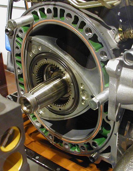
dikenal dengan mesin yang irit, efisiensi tinggi, dan ramah lingkungan. digunakan pertama kali oleh citroen M35, lalu digunakan mazda Eunos Cosmo, RX7, dan RX8.

Spoiler for RADIAL ENGINE
sistem kerjanya sama dengan mesin mobil/motor pada umumnya. hanya saja konfigurasinya berbentuk bintang. digunakan pada pesawat tempur propeler PD1 dan PD2.

Spoiler for QUASITURBINE
sistem kerja mirip dengan Wankel, namun mesin ini mempunyai 4 ruang. mesin ini tergolong modern karena baru selesai dikembangkan tahun 1996. belum ada laporan tentang alat yg memakai mesin ini.

Spoiler for NAPIER DELTIC

digunakan pada kapal perang modern dan lokomotif diesel modern.

ROTARY DIESEL INJECTION PUMP MODEL


Deskripsi

Trainer ini berupa pompa injeksi jenis rotary yang dipotong pada bagian tertentu untuk menampilkan komponen-komponen bagian dalam dan fungsi kerjanya sangat bagus untuk identifikasi komponen-komponen dan cara kerja dari; element, control rack, saluran tekanan tinggi, pompa delivery, dan governor centrifugal.
Trainer ini sangat cocok digunakan sebagai alat peraga di dalam pengajaran tentang ilmu diesel.

Komponen Terpasang
- Pompa injeksi rotary asli
- 4 elemen dengan pompa delivery
- Governor centrifugal

Sumber Daya
- Tanpa Battery

Dimensi
- Panjang:380 mm
- Lebar:210 mm
- Tinggi:220 mm

Warna
- Silver Met

Bahan
- Stand : Pipa 1,5 inch
- Papan : Kayu

Aksesoris - Jobsheet

INJECTION PUMP MODEL - IN LINE TYPE


Deskripsi

Trainer ini berupa pompa injeksi jenis in line yang dipotong pada bagian tertentu untuk menampilkan komponen-komponen bagian dalam dan fungsi kerjanya sangat bagus untuk identifikasi komponen-komponen dan cara kerja dari; element, control rack, saluran tekanan tinggi, pompa delivery, dan governor centrifugal.
Trainer ini sangat cocok digunakan sebagai alat peraga di dalam pengajaran tentang ilmu diesel.

Komponen Terpasang
- Pompa injeksi in line asli
- 4 elemen dengan pompa delivery
- Governor centrifugal

Sumber Daya
- Tanpa Battery

Dimensi
- Panjang:30 mm
- Lebar:21 mm
- Tinggi:28 mm

Berat
- 20 kg

Warna
- Silver Met Kombinasi

Bahan
- Stand : Besi
- Papan : Kayu

Aksesoris
- Jobsheet

ELECTRONIC IGNITION SYSTEM - TCI INDUCTIVE


Deskripsi

Trainer ini dirakit dari komponen-komponen asli sistem pengapian TCI Induction yang diletakkan pada papan acrylic, dapat digunakan untuk identifikasi konstruksi sistem pengapian elektronik TCI Inductif. Juga dapat dipakai sebagai alat praktik pengukuran saat pengapian, sudut dwell, fungsi dan kerja dari sistem pengapian TCI Induktif.

Komponen Terpasang
- Kotak Sekering
- Kunci Kontak
- Koil
- Distributor
- Unit Kontrol
- Ampere Meter
- Volt Meter
- Busi
- Kabel busi
- Kabel Konektor
- Motor Listrik
- dll.

Sumber Daya
- Battery 12V/40AH

Dimensi
- Panjang:1080 mm
- Lebar:400 mm
- Tinggi:850 mm

Warna
- Silver Met

Bahan
- Rangka : Besi
- Papan : Mika

Aksesoris
- Jobsheet

FOUR STROKES ENGINE MODEL

FOUR STROKES ENGINE MODEL


Deskripsi

Trainer ini adalah mesin sepeda motor 4 tak yang dipotong pada bagian tertentu untuk menampilkan mekanisme gerak piston 4 tak, mekanisme buka tutup katup, sistem pengaliran pelumas, sistem starter, sistem pemindahan tenaga. Sangat cocok untuk menjelaskan sistem kerja mesin 4 tak di dalam kelas.

Komponen Terpasang
- Mesin sepeda motor 4 tak
- Karburator
- dll.

Sumber Daya
- Tanpa Battery

Dimensi
- Panjang : 400 mm
- Lebar : 400 mm
- Tinggi : 500 mm

Berat
- 50 kg

Warna
- Silver Met Kombinasi

Bahan
- Stand : Pipa 1,5 inch
- Papan : Kayu

Aksesoris
- Jobsheet

Tuesday, April 12, 2011

How the Radio Spectrum Works

You've probably heard about "AM radio" and "FM radio," "VHF" and "UHF" television, "citizens band radio," "short wave radio" and so on. Have you ever wondered what all of those different names really mean? What's the difference between them?

A radio wave is an electromagnetic wave propagated by an antenna. Radio waves have different frequencies, and by tuning a radio receiver to a specific frequency you can pick up a specific signal.

the radio spectrum band

In the United States, the FCC (Federal Communications Commission) decides who is able to use which frequencies for which purposes, and it issues licenses to stations for specific frequencies. See How Radio Works for more details on radio waves.

When you listen to a radio station and the announcer says, "You are listening to 91.5 FM WRKX The Rock!," what the announcer means is that you are listening to a radio station broadcasting an FM radio signal at a frequency of 91.5 megahertz, with FCC-assigned call letters of WRKX. Megahertz means "millions of cycles per second," so "91.5 megahertz" means that the transmitter at the radio station is oscillating at a frequency of 91,500,000 cycles per second. Your FM (frequency modulated) radio can tune in to that specific frequency and give you clear reception of that station. All FM radio stations transmit in a band of frequencies between 88 megahertz and 108 megahertz. This band of the radio spectrum is used for no other purpose but FM radio broadcasts.
In the same way, AM radio is confined to a band from 535 kilohertz to 1,700 kilohertz (kilo meaning "thousands," so 535,000 to 1,700,000 cycles per second). So an AM (amplitude modulated) radio station that says, "This is AM 680 WPTF" means that the radio station is broadcasting an AM radio signal at 680 kilohertz and its FCC-assigned call letters are WPTF.
On the next page, learn more about about frequency bands and the frequencies that common gadgets use.

How Radio Scanners Work


radio scanner
Photo courtesy HowStuffWorks Shopper
The air around you is bursting with radio waves. You know that you can flip on the AM/FM radio in your car and receive dozens of stations. You can flip on a CB radio and receive 40 more. You can flip on a TV and receive numerous broadcast channels. Cell phones can send and receive hundreds of frequencies. And this is just the tip of the radio spectrum iceberg. Literally tens of thousands of other radio broadcasts and conversations are zipping past you as you read this article -- police officers, firefighters, ambulance drivers, paramedics, sanitation workers, space shuttle astronauts, race car drivers, and even babies with their monitors are transmitting radio waves all around you at this very moment! To tap into this ocean of electromagnetic dialogue and hear what all of these people are talking about, all you need is a scanner. A scanner is basically a radio receiver capable of receiving multiple signals. Generally, scanners pick up signals in the VHF to UHF range (see How the Radio Spectrum Works for details on these frequency bands).
Radio scanners are very portable and affordable. In this article, we will look at the basics of scanner operation, examine radio scanning as a hobby, and show you how to get started listening to public airwaves you may not have known existed!
Scanner Basics
Scanners typically operate in three modes:
  • Scan
  • Manual scan
  • Search
In scan mode, the receiver constantly changes frequencies in a set order looking for a frequency that has someone transmitting. Lights or panel-mounted displays show what channel or frequency is in use as the scanner stops on a given frequency. The frequencies can be preprogrammed on some models or manually set on practically all models.
In manual scan mode, the user taps a button or turns a dial to manually step through preprogrammed frequencies one frequency at a time.
In search mode, the receiver is set to search between two sets of frequencies within a given band. This mode is useful when a user does not know a frequency, but wants to know what frequencies are active in a given area. If the frequency the scanner stops at during a search is interesting, the user can store that frequency in the radio scanner and use it in scan mode.

How Satellite Radio Works


satellite radio graphic We all have our favorite radio stations that we preset into our car radios, flipping between them as we drive to and from work, on errands and around town. But when you travel too far away from the station, the signal breaks up and fades into static. Most radio signals can only travel about 30 or 40 miles (48 to 64 kilometers) from their source. On long trips, you might have to change radio stations every hour or so as the signals fade in and out. And it's not much fun scanning through static trying to find something -- anything -- to listen to.
Now, imagine a radio station that can broadcast its signal from more than 22,000 miles (35,000 kilometers) away and then come through on your car radio with complete clarity. You could drive from Tacoma, Wash., to Washington, D.C., without ever having to change the radio station! Not only would you never hear static interfering with your favorite tunes, but the music would be interrupted by few or no commercials.
XM Satellite Radio and Sirius Satellite Radio each launched such a service at the beginning of the 21st century. Satellite radio, also called digital radio, offers uninterrupted, near CD-quality music beamed to your radio from space.
In February 2007, XM Satellite Radio and Sirius Satellite Radio announced their plans to merge into a single company. XM and Sirius were both in debt, and believed a merger would quickly solve that problem. They thought that the merger would also lead to lower prices and more programming choices for consumers. Some people were skeptical about the two companies joining, though, fearing a monopoly would only reduce competition, raise prices and affect consumers poorly. Sirius and XM received approval from the U.S. Department of Justice, but the companies couldn't move until the FCC begrudgingly allowed the merger to go forward in July 2008. The new company goes by the name Sirius XM Radio.

Even though XM and Sirius had financial trouble, satellite radio still has a fairly strong fan base. The new Sirius XM company has more than 18 million subscribers [source: Sirius XM]. ­Car manufacturers have been installing satellite radio receivers in some models for a few years now, and several portable satellite radio receivers are available from a variety of electronics companies. In this article, you'll learn what separates satellite radio from conventional radio and about the equipment you'll need to pick up satellite radio signals. ­

Friday, April 8, 2011

Automobile Engines

Back to Family Car's Classroom on the Web 
A Short Course on
Automobile Engines
by Charles Ofria
 Typical Automobile Engine
Internal combustion gasoline engines run on a mixture of gasoline and air.  The ideal mixture is 14.7 parts of  air to one part of gasoline (by weight.)  Since gas weighs much more than air, we are talking about a whole lot of air and a tiny bit of gas.   One part of gas that is completely vaporized into 14.7 parts of air can produce tremendous power when ignited inside an engine.
Let's see how the modern engine uses that energy to make the wheels turn.
Air enters the engine through the air cleaner and proceeds to the throttle plate. You control the amount of air that passes through the throttle plate and into the engine with the gas pedal.  It is then distributed through a series of passages called the intake manifold, to each cylinder.  At some point after the air cleaner, depending on the engine, fuel is added to the air-stream by either a fuel injection system or, in older vehicles, by the carburetor.
Once the fuel is vaporized into the air stream, the mixture is drawn into each cylinder as that cylinder begins its intake stroke.  When the piston reaches the bottom of  the cylinder, the intake valve closes and the piston begins moving up in the cylinder compressing the charge.  When  the piston reaches the top, the spark plug ignites the fuel-air mixture causing a powerful expansion of the gas, which pushes the piston back down with great force against the crankshaft, just like a bicycle rider pushing against the pedals to make the bike go.
Let's take a closer look at this process.
Engine Types
The majority of engines in motor vehicles today are four-stroke, spark-ignition internal combustion engines.  The exceptions like the diesel and rotary engines will not be covered in this article. Typical Cylinder ArrangementsThere are several engine types which are identified by the number of cylinders and the way the cylinders are laid out.  Motor vehicles will have from 3 to 12 cylinders which are arranged in the engine block in several configurations. The most popular of them are shown on the left.  In-line engines have their cylinders arranged in a row.   3, 4, 5 and 6 cylinder engines commonly use this arrangement. The "V" arrangement uses two banks of cylinders side-by-side and is commonly used in V-6, V-8, V-10 and V-12  configurations. Flat engines use two opposing banks of cylinders and are less common than the other two designs.  They are used in engines from Subaru and Porsche in 4 and 6 cylinder arrangements as well as in the old VW beetles with 4 cylinders.  Flat engines are also used in some Ferraris with 12 cylinders
Most engine blocks are made of cast iron or cast aluminum..Piston and Connecting Rod
Each cylinder contains a piston that travels up and down inside the cylinder bore.  All the pistons in the engine are connected through individual connecting rods to a common crankshaft.
CrankshaftThe crankshaft is located below the cylinders on an in-line engine, at the base of the V on a V-type engine and between the cylinder banks on a flat engine. As the pistons move up and down, they turn the crankshaft just like your legs pump up and down to turn the crank that is connected to the pedals of a bicycle.
Typical Cylinder HeadA cylinder head is bolted to the top of each bank of cylinders to seal the individual cylinders and contain the combustion process that takes place inside the cylinder.  Most cylinder heads are made of cast aluminum or cast iron.  The cylinder head contains at least one intake valve and one exhaust valve for each cylinder. This allows the air-fuel mixture to enter the cylinder and the burned exhaust gas to exit the cylinder.  Engines have at least two valves per cylinder, one intake valve and one exhaust valve. Many newer engines are using multiple intake and exhaust valves per cylinder for increased engine power and efficiency.   These engines are sometimes named for the number of valves that they have such as "24 Valve V6" which indicates a V-6 engine with four valves per cylinder.  Modern engine designs can use anywhere from 2 to 5 valves per cylinder.
CamshaftThe valves are opened and closed by means of a camshaft. A camshaft is a rotating shaft that has individual lobes for each valve.  The lobe is a "bump" on one side of the shaft that pushes against a valve lifter moving it up and down. When the lobe pushes against the lifter, the lifter in turn pushes the valve open.  When the lobe rotates away from the lifter, the valve is closed by a spring that is attached to the valve.   A common configuration is to have one camshaft located in the engine block with the lifters connecting to the valves through a series of linkages.  The camshaft must be synchronized with the crankshaft so that the camshaft makes one revolution for every two revolutions of the crankshaft.  In most engines, this is done by a "Timing Chain" (similar to a bicycle chain) that connects the camshaft with the crankshaft. Newer engines have the camshaft located in the cylinder head directly over the valves.  This design is more efficient but it is more costly to manufacture and requires multiple camshafts on Flat and V-type engines.  It also requires much longer timing chains or timing belts which are prone to wear.  Some engines have two camshafts on each head, one for the intake valves and one for the exhaust valves.  These engines are called Double Overhead Camshaft (D.O.H.C.) Engines while the other type is called Single Overhead Camshaft (S.O.H.C.) Engines.  Engines with the camshaft in the block are called Overhead Valve (O.H.V) Engines.
Now when you see "DOHC 24 Valve V6", you'll know what it means.
How an Engine Works
Since the same process occurs in each cylinder, we will take a look at one cylinder to see how the four stroke process works.
The four strokes are Intake, Compression, Power and Exhaust. The piston travels down on the Intake stroke, up on the Compression stroke, down on the Power stroke and up on the Exhaust stroke. Running Engine
  • Intake
    As the piston starts down on the Intake stroke, the intake valve opens and the fuel-air mixture is drawn into the cylinder (similar to drawing back the plunger on a hypodermic needle to allow fluid to be drawn into the chamber.)
    When the piston reaches the bottom of the intake stroke, the intake valve closes, trapping the air-fuel mixture in the cylinder.
  • Compression
    The piston moves up and compresses the trapped air fuel mixture that was brought in by the intake stroke. The amount that the mixture is compressed is determined by the compression ratio of the engine.  The compression ratio on the average engine is in the range of 8:1  to 10:1.
    This means that when the piston reaches the top of the cylinder, the air-fuel mixture is squeezed to about one tenth of its original volume.
  • Power
    The spark plug fires, igniting the compressed air-fuel mixture which produces a powerful expansion of the vapor.  The combustion process pushes the piston down the cylinder with great force turning the crankshaft to provide the power to propel the vehicle. Each piston fires at a different time, determined by the engine firing order. By the time the crankshaft completes two revolutions, each cylinder in the engine will have gone through one power stroke.
  • Exhaust
    With the piston at the bottom of the cylinder, the exhaust valve opens to allow the burned exhaust gas to be expelled to the exhaust system.   Since the cylinder contains so much pressure, when the valve opens, the gas is expelled with a violent force (that is why a vehicle without a muffler sounds so loud.)    The piston travels up to the top of the cylinder pushing all the exhaust out before closing the exhaust valve in preparation for starting the four stroke process over again.
Oiling System
Oil is the life-blood of the engine. An engine running without oil will last about as long as a human without blood. Oil is pumped under pressure to all the moving parts of the engine by an oil pump.  The oil pump is mounted at the bottom of the engine in the oil pan and is connected by a gear to either the crankshaft or the camshaft.  This way, when the engine is turning, the oil pump is pumping.  There is an oil pressure sensor near the oil pump that monitors pressure and sends this information to a warning light or a gauge on the dashboard. When you turn the ignition key on, but before you start the car, the oil light should light, indicating that there is no oil pressure yet, but also letting you know that the warning system is working.  As soon as you start cranking the engine to start it, the light should go out indicating that there is oil pressure.
Engine Cooling
Internal combustion engines must maintain a stable operating temperature, not too hot and not too cold.  With the massive amounts of heat that is generated from the combustion process, if the engine did not have a method for cooling itself, it would quickly self-destruct.  Major engine parts can warp causing oil and water leaks and the oil will boil and become useless.
While some engines are air-cooled, the vast majority of engines are liquid cooled.   The water pump circulates coolant throughout the engine, hitting the hot areas around the cylinders and heads and then sends the hot coolant to the radiator to be cooled off. For more information on the cooling system,
Engine Balance
Flywheel  A 4 cylinder engine produces a power stroke every half crankshaft revolution, an 8 cylinder, every quarter revolution.  This means that a V8 will be smother running than a 4.  To keep the combustion pulses from generating a vibration,  a flywheel is attached to the back of the crankshaft.  The flywheel is a disk that is about 12 to 15 inches in diameter. On a standard transmission car, the flywheel is a heavy iron disk that doubles as part of the clutch system. On automatic equipped vehicles, the flywheel is a stamped steel plate that mounts the heavy torque converter.  The flywheel uses inertia to smooth out the normal engine pulses.
Balance Shaft  Some engines have an inherent rocking motion that produces an annoying vibration while running.  To combat this,  engineers employ one or more balance shafts. A balance shaft is a heavy shaft that runs through the engine parallel to the crankshaft. This shaft has large weights that, while spinning, offset the rocking motion of  the engine by creating an opposite rocking motion of their own.
Copyright ©  2000-2007, SmartTrac Computer Systems, Inc.

Engine Partners With US Sydney For SBS Immigration Nation

sbsimmigration-1

sbsimmigration-2

sbsimmigration-3

Engine Partners With US Sydney For SBS Immigration Nation

According to Engine EP Adam Wells the promos they recently created for SBS’ new documentary series Immigration Nation: The Secret History of Us have raised more than a few eyebrows.
Wells explained, “The project came about after our CD Simon Robson (Knife Party) and I met with the team at Us Sydney. They presented four scripts for promos about a 3-part documentary series tracing Australia’s chequered immigration policy from the 1900s to the present day. With that kind of subject matter it was clear controversy wasn’t going to be far away.”
Robson took away the four scripts, one for a ‘coming soon’ promo and the others all based around specific time periods from the White Australia policy to multiculturalism and began work on developing the concepts. Engine’s Producer on the Immigration Nation promos Amelia Peacocke said, “Immigration Nation was a thoroughly inspiring project to work on with the agency and Engine teams developing a very creative and trusting relationship on the production. One of the challenges we came across was how best to showcase the idea that the talent in each of the three episodes was holding a dark secret buried beneath their positive message about Australia's immigration policy. The agency came to Engine with the challenge of making the characters spin around and develop an execution that saw the talent being shot and composited so that they appeared to be the same person back to back. The execution of this idea really helped to really drive home the message.”
The Engine team had three set time periods to work with, the 1900s, 1950s and the present day – one for each episode of the series. Robson added, “A point to note here is that the ‘back to back’ post production effect in each promo where, when the character finishes their piece, they spin 180 degrees on a turntable to highlight the two-faced and double-sided slant to some of Australia’s immigration policies also represents Australia’s alter-ego - the small print or terms and conditions that went hand in hand with the practical come one, come all message.”
For the 1900’s promo Robson and his team cast and selected talent for a dark silent film. In the 1950’s promo Robson used the same format but this time casting a post war UK cinema style ‘Walter Kronkite’ figure with a visual projected behind him ‘Hitchcock-style’, selling Australia as the land of fertility where everyone could come and build a great future. When the character flips to his alter ego the background visual burns out leaving only the brutal reality of the real terms and conditions for entry.
Robson added, “Both spots from the past were meant to cause a reaction and raise eyebrows. The modern day promo takes it one step further with a female current affairs pundit selling today’s benefits of Australia’s great multi-cultural approach only to flip as the studio environment darkens to reveal the true terms and conditions over the course of history.”
Perhaps the most impactful of the four promos was the ‘coming soon’ spot which also proved creatively challenging as it needed to deliver a very complex message.
Robson explained, “The client and agency had seen some of my past work including Taking Liberties and What Barry Says which involve interesting animation and typographical effects and wanted these looks for the ‘coming soon’ promo. This gave us great scope to create something unusual for Australian television.”
Robson creatively directed the services of top illustrator Pete McDonald and worked with the typography skills of Luca Ionescu of Like Minded Studios, brought on board by US Sydney to work on the project, to bring together a series of unique elements for the spot.
Robson continued, “This is very much the model and approach used by large international agencies – bring in the best talent for each job and work with them in-house. It worked really well with Pete and Luca’s clever images and typography helping to create a ‘moving stream of consciousness’ where Utopian messages revealed themselves in the landscape, before coming abruptly to a halt to deliver the sobering truth. As a result the ‘coming soon’ promo communicates a real Australian narrative that depicts our natural resources of wheat, meat and timber and cleverly integrates them with the mixed messages around immigration.”
Engine’s Senior Flame Artist Lee Sandiford was then tasked with doing an authentic grade for each era. As Sandiford explained, there were some particular creative challenges that needed to be overcome. He said, “We did an initial test on a basic version of the concept, showed it to the client and they loved it. Each era had a different look, feel, grade and colour. The blacks and whites were different and we had to degrade the images and footage to make them look like an old film reel that was suffering with too much light from a non-existent projector. The 180-degree turnaround effect had to be fast enough to be snappy but slow enough that the viewer can see it’s two sides of the same person.”
According to Adam Wells the SBS Immigration Nation promos are very much the shape of things to come for the company. He concluded, “This is a very good example of a complete top to tail campaign done completely at Engine. From casting, wardrobe, shooting footage and creating characters through 2D, 3D and post it was all taken care of by our in-house team. This is something that we are being asked to do more and more of and we see very much as the future of our industry.”
Immigration Nation aired at 8.30pm on Sundays on SBS One. To view the promos and for more information on Immigration Nation go to: http://www.behance.net/gallery/IMMIGRATION-NATION/893164
And http://www.sbs.com.au/immigrationnation
Credits:
Client: SBS
Agency: US Sydney
Production Company: Engine
Director: Simon Robson
US Sydney / Creatives:
Alex Tracy (Account Director)
Josh Moore (Executive Creative Director)
Nigel Clark (Copywriter)
Tim Chenery (Art Director)
Amelia Peacocke (Producer)
Sacha Moore (Agency Producer)
Tim Stuart (Account manager)
Animation Credits:
Executive Producer: Adam Wells
Typography: Luca @ Like Minded
Illustration: Pete J McDonald
Lead 2D animation: Robert Grieves
Animation: Marko Pfann
3D: Shaun Schellings & Dam

Chevy 454-cid V-8 Engine

For the 1970 model year, Chevrolet announced a 454-cid expansion of the Mark IV, available for Monte Carlo, Chevelle, the big Chevrolet, and Corvette. At the same time, two 400-cid engines appeared on the specs charts, but they were totally different. One was actually a slightly larger 402 derivative of the big-block 396. The other that was a small-block unit based on the thick-web 350 that was a direct descendant of the fabled 327.
Chevy engineers had to bend some of their rules to get as much as 400 cubes from the small-block with its 4.40-inch bore spacing and short deck height. That configuration imposed a definite limit on how far stroke could be stretched without pulling the pistons too far out of their holes. Boring out to 4.125 inches left less than a quarter-inch between the bores, and that had to be solid metal, with no water jacketing to separate the cylinders. The 350's 3.48-inch stroke was extended to 3.75 inches, which necessitated larger diameter (2.65 inches instead of 2.45) main bearings to assure adequate overlap between the mains and the crankpin journals. That, in turn, required a new, heftier, and heavier crankshaft. The longer stroke caused an increase in piston speed that aggravated the greater heat-sensitivity of the siamesed cylinders. As a result, the small-block Turbo-Fire 400 had no potential as a performance engine. It did have advantages for emissions control, however, because of its more favorable surface-to-volume ratio. The most Chevy ever got from it was a rated 265 bhp.
454 chevy v8 engine
Publications International, Ltd.
The first 454-cid Mark IV enlargement arrived for 1970. Shown is the 460-bhp LS-7 unit with 3x2 carbs.
By contrast, the Turbo-Jet 400 belonged to the big-block Mark IV family. It had almost the same cylinder dimensions as the small-block unit (4.126 x 3.76 inches), but delivered a hefty 330 bhp on 10.25:1 compression for 1970. The 454 launched that same year was basically the Mark IV design, with stroke extended to a full 4.00 inches. It came in two forms: the 390-bhp LS-5, with hydraulic lifters, 10.25:1 compression, and a four-barrel Rochester carb; and the 460-bhp LS-7, with solid lifters, 11.25:1 compression, and four-barrel Holley, plus a special higher-left camshaft and transistorized ignition.
The big-blocks were the culmination of Chevrolet's performance engine development. But these potent powerplants wouldn't take kindly to the anti-smog devices needed to meet stiffening emission standards beginning in 1973. That year, America would get its first "fuel shock," which ultimately would sentence big-inch high-performance cars to oblivion. Up to that time, Tonawanda was turning out 300,000 Mark IV V-8s annually. By the end of the 1976 model year, the big-block engine family would be gone.

Chevy 265-cid V-8 Engine

Shortly after Ed Cole took over as Chevrolet chief engineer, GM board chairman Alfred P. Sloan asked him about his plans for the department. Although they included tripling the engineering staff, Sloan just waved him on. Quipped then-GM president Charles Wilson to Cole, "I'll bet that's the first time you ever had your plans approved without submitting them."
To alter Chevrolet's time-honored image from builder of mundane people-movers to performance-car specialist, Cole knew he would need a V-8 engine. His predecessor, Ed Kelley, had toyed with the V-6 and a 231 cubic-inch V-8, both of which Cole rejected. But, he didn't have much time to consider alternatives. When all the development phases were accounted for, there would be just 15 weeks in which to design a new powerplant for the 1955 model line. With the help of Kelley and motor engineer Harry Barr, Cole made it.
265 chevy v8 engine
Publications International, Ltd.
Considered a benchmark engine design even in its day, Chevy's lightweight and efficient 265 V-8 has been a performance favorite for two generations.
­ "I had worked on V-8 engines all my professional life," Cole said later. "I had lived and breathed engines. Barr and I were always saying how we would do it if we ever design a new engine. You just know you want five main bearings - there's no decision to make. We knew that a certain bore/stroke relationship was the most the most compact. We knew we'd like a displacement of 265 cubic inches and the automatically established the bore and stroke. And we never changed any of this. We released our engine for tooling direct from the drawing boards - that's how crazy and confident we were."
Of course, even a ground-up engine has to be designed within certain parameters. Since it was intended for Chevrolet, the new V-8 had to be relatively inexpensive to build and efficient in operation. It need not be a poor engine - and it was anything but - yet it had to be a model of simplicity and production economics, which it was.

How to check car parts - car engine


ever wondered how to check certain car parts when buying a car, well here is our new section and its all about how to check car parts so you know your getting your moneys worth.

Our first post is on checking a car engine. This is a much needed post because a salesman can make up a nice looking car, but you don’t know whats underneath the hood.

Firstly you could get the car engine and the entire car checked by a specialist. but if not then here are a few simple rules.

Firstly check the car engine levels e.g. oil, and water. The oil should be dark black for a diesel and a yellow/orange color for petrol. If the oil level is low then you can suspect lack of maintenance and possible damage in the future. It may also represent a leak so check for those.

Try as much as you can to look at the internal car engine parts. These hidden parts can give allot away. What you should look for in the car engine parts is sludge from the oil. If there is a buildup of oil sludge it suggests that the oil has not been changed in a while and bad maintenance has occurred.

If you can check the oil pressure then do so because low oil pressure means the engine is on the way out. Other checks should be on any repairs made to the vehicle. are they hiding bad parts?

Many people check the car engine oil levels and water levels of their washer but never the engine water which contains water and antifreeze. If this is low or you find oil in it it may suggest a engine radiator problem. It should be clean and transparent and within the min and max levels, else you don’t buy the vehicle or get it fixed immediately.

One obvious test is to drive it. From this you can tell some errors such as lights coming on and increased emissions (e.g. smoke) from the exhaust. Note there should be no smoke at all. You can also listen to the car engine, does it sound normal? does it feel right?

Finally a often forgotten rule, check the millage and if it has loads of millage (over 100 000 miles) then think about what your going to use the car for, if its anything major then get a lower millage vehicle.

Remember if the car engine is damaged the car wont last long and you will have have thrown your money away

Wednesday, April 6, 2011

How HEMI Engines Work

If you like cars, then you have probably heard of the HEMI engine. If you were born in the 1960s or before, you remember the phenomenon created by Chrysler's HEMI engines in the 1950s, '60s and '70s. If you follow muscle cars or drag racing, you know that the 426 HEMI engine is a popular engine because of its performance. You've probably also heard of the HEMI engines that Chrysler began using in 2003 Dodge trucks.

Car Engine Image Gallery

5.7-liter HEMI Magnum V-8 engine 
 
But even if you know little or nothing about cars and engines, the word "HEMI" might still mean something to you. The word has become a synonym for big, powerful engines. In this article, you'll learn about the HEMI engine and find out why engines using the HEMI design are such awesome machines. Birth of the HEMI
The HEMI engine for automobiles was born in 1948 -- Harry Westlake and several others developed a Hemi 6-cylinder engine for Jaguar. A few years later, in 1951, Chrysler introduced a 180-horsepower HEMI V-8 engine on several models. The Chrysler HEMI engine had a displacement of 331 cubic inches (5.4 liters), so it is known as the "331 HEMI."
These days, 180 horsepower sounds like nothing. But in 1951, 180 horsepower was unheard of. It was an amazing amount of power for the day, and it fueled the "HEMI legend."

Dual Ghia powered by a 392 HEMI
Photo courtesy DaimlerChrysler
Dual Ghia powered by a 392 HEMI
Chrysler continued improving the HEMI design, releasing a 354-cubic-inch design in 1956, a 392 cubic-inch design in 1957, and ultimately a 426-cubic-inch (7-liter) version in 1964. The 426 engine set the HEMI legend in stone when it won first, second and third place in the 1964 Daytona 500 NASCAR race. The 426 street HEMI came out in 1965, producing 425 horsepower.
The 426 block and heads are still available today from Dodge. The 426 HEMI is a popular power plant for drag racing, funny cars and muscle cars.
In the next section, we'll look at how the HEMI is designed for power.
 

Chevy 283-cid V-8 Engine

The great small-block Chevy V-8 reached its second important development plateau in 1957. While the 265 was retained as the "base" engine this model year, the big news was the new 283-cid enlargement, achieved by punching out bore to 3.88 inches. In its mildest tune it produced 185 bhp at 4600 rpm; a four-barrel card brought this up to 220 bhp; two fours resulted in either 245 or 270; and Chevy's new "Ramjet" fuel injection system boosted output to no less than 250 or 283. The last was the ultimate, achieving the magic goal of one horsepower per cubic inch, and was offered with close-ratio three-speed manual transmission only.
283 chevy v8 engine
Publications International, Ltd.
The Turbo-Fire V-8 was bored out to 283 cid for 1957, would be a Chevy performance mainstay into the '70s.
The "fuelie" was carefully developed for good reliability. Mechanical valve lifters substituted for hydraulics when FI was specified. Longer-reach spark plugs with the metal deflection shields were used to protect wiring and plug caps from manifold heat. The top block was a thicker casting to prevent cylinder wall distortion though over-tight hold-down bolts. Fuel passages were tapered, increasing in cross-sectional area toward the inlet ports and in the "ram's horn" exhaust manifold to provide better scavenging and increased volumetric efficiency. There was new distributor, with the breaker points directly above the shaft bearing to help reduce fluctuations in the gap setting. And the front and intermediate main bearings were 0.063-inch thicker.
Though made by GM's Rochester carburetor division, the Ramjet fuel injection system was designed almost entirely by the Engineering Staff, simplified for production by Harry Barr and Zora Arkus-Duntov. It consisted of three main components: fuel meter, manifold assembly, and air meter, replacing intake manifold carburetor. The unit took in air first, then injected fuel directly into each intake port for mixing. The amount of fuel used was very precisely controlled, again for better volumetric effiency and mileage. Cold-weather starting and warm-up were improved, and the unit by itself boosted output by about 5 bhp compared to the twin four-barrel carbureted engine. Chevrolet claimed that FI eliminated manifold icing, and reduced the tendency to stall when cornering hard.

Chevy 265-cid V-8 Engine

Massive Engines Videos
  • More Auto Videos »
Shortly after Ed Cole took over as Chevrolet chief engineer, GM board chairman Alfred P. Sloan asked him about his plans for the department. Although they included tripling the engineering staff, Sloan just waved him on. Quipped then-GM president Charles Wilson to Cole, "I'll bet that's the first time you ever had your plans approved without submitting them."
To alter Chevrolet's time-honored image from builder of mundane people-movers to performance-car specialist, Cole knew he would need a V-8 engine. His predecessor, Ed Kelley, had toyed with the V-6 and a 231 cubic-inch V-8, both of which Cole rejected. But, he didn't have much time to consider alternatives. When all the development phases were accounted for, there would be just 15 weeks in which to design a new powerplant for the 1955 model line. With the help of Kelley and motor engineer Harry Barr, Cole made it.
265 chevy v8 engine
Publications International, Ltd.
Considered a benchmark engine design even in its day, Chevy's lightweight and efficient 265 V-8 has been a performance favorite for two generations.
­ "I had worked on V-8 engines all my professional life," Cole said later. "I had lived and breathed engines. Barr and I were always saying how we would do it if we ever design a new engine. You just know you want five main bearings - there's no decision to make. We knew that a certain bore/stroke relationship was the most the most compact. We knew we'd like a displacement of 265 cubic inches and the automatically established the bore and stroke. And we never changed any of this. We released our engine for tooling direct from the drawing boards - that's how crazy and confident we were."
Of course, even a ground-up engine has to be designed within certain parameters. Since it was intended for Chevrolet, the new V-8 had to be relatively inexpensive to build and efficient in operation. It need not be a poor engine - and it was anything but - yet it had to be a model of simplicity and production economics, which it was.

Chevy 348-cid V-8 Engine

The first big-block Chevy V-8 was introduced in 1958 as an optional alternative to the small-block engine. It was not related in any way to its classic predecessor, being new from the ground up. Neither has it been regarded as one of the highlights in Chevy engine history. Although good in its way, it was simply outclassed by the "fuelie" 283 before it and by the 409 which took over at the head of the line for 1962. But the 348 was the largest and most powerful Chevrolet engine you could buy in 1958-61, and deserves at least a brief mention.
As the 265/283 was first known as "Turbo-Fire," the 348 was dubbed "Turbo-Thrust," but the factory knew it better as the "type W." This designation stemmed from the characteristic shape on the outside edge of the rocker covers, something that was much less unique as we moved into the 60s. The "W" was intended for the new generation of a much larger and heavier Chevrolets born in 1958 that blossomed into the full-blown 119-inch-wheelbase cruisers of 1959.
348 chevy v8 engine
Publications International, Ltd.
The 1958 version of the Turbo-Thrust 348 V-8. Though it started as a truck engine, it formed the basis of the legendary 409, introduced in mid-1961.
­ With a bore and a stroke of 4.125 x 3.25 inches and 9.5:1 compression ratio, the 348 developed 250 bhp at 4000 rpm and 355 pounds-feet of torque at 2800 rpm. Combustion chambers were cylindrical wedges formed by flat-bottom heads that rested against the block faces at a 16 degree angle. The cast-aluminum pistons were machined with 16-degree dual-sloping upper surfaces. Hydraulic valve lifters were used, as they were in the small-block V-8s (except fuel injected units). "Because of the lack of restrictions to passage of the fuel/air mixture in the heads and because half of the piston is closer to the head than the other half, turbulence is tremendous and volumetric efficiency should be excellent," observed Motor Trend. The "W" came standard with dual exhausts and four-barrel carburetor, but was not offered with fuel injection - something Chevy had had problems with, and was generally encouraging only for Corvettes.
The 348's highest stage of development appeared for 1960 - two four-barrel carburetors good for a rated 355 horsepower. It continued in this form for the 1961 model year before disappearing in favor of the 409.
The 348 should be remembered not as a mighty powerhouse, but as a smooth and reliable big-block for the new, larger Impala. Its 10-second 0-60 mph capability was about the norm for 1958 - hardly the kick-in-the-back acceleration provided by the FI or dual-quad 283s. Significantly, Chevrolet offered very little hop-up equipment for the "W" for the simple reason that it never was really intended as a high-performance mill. In 1958, of course, Chevrolet was outwardly abiding by the Automobile Manufacturers Association (AMA) decision to "discourage" (or at least not advertise) racing, and the 348 fit right in with the Division's public posture. Performance enthusiasts would have to be content with the hotter versions of the 283 through 1961. Happily, these powered some of the most memorable of the "performance" Chevys.

Chevy 396-cid V-8 Engine

Early in 1963, a mysterious new Chevrolet 427 V-8 appeared at Daytona International Speedway. After being shocked by its acceleration and speed, rivals who were able to look at it with the rocker covers off noticed its odd valve angles, and nicknamed it the "Porcupine" engine. In the 500-mile race, the Chevy simply sped away, leaving all other cars behind, and lapped at average speeds up to 166 mph before dropping out-due to unspecified engine failure. Shortly after that, GM's top management put a ban on racing activities by its car divisions, and no more was heard of the "Porcupine." However, development work on it continued unabated at the GM Technical Center in Warren, Michigan. It resurfaced in the spring of 1965 as a high-performance option for the Chevelle, the full-size Chevrolet, and the Corvette, with capacity to cut 396 cid.
Design and development work on the "Porcupine" is credited to a team consisting of Richard L. Keinath, assistant staff engineer; Herbert G. Sood, project engineer; and William J. Polkinghorne. Keinath had helped Don McPherson design the four-and six-cylinder ChevyII engines in 1960-1961, and had been working on V-8 projects since then. He had joined General Motors in 1950, arriving at Chevrolet in 1956. However, the idea for the "Porcupine" valvetrain and overall engine design came from Robert P. Benzinger, who had laid out and detailed the all-aluminum Corvair flat six, and was gaining recognition among Chevrolet's technical staff as Division's top engine man.
chevy 396-cid V-8 Engine
Publications International, Ltd.
Chevy's 396-cid V-8 "Porcupine" Engine
What was new and unusual about the valve gear was that it resulted from working "backwards." Normally, an engine designer starts with the combustion chambers, and arranges the valves so they can be operated by simple, straightforward mechanisms. Benzinger felt that better results could be obtained by giving attention to breathing rather than just locating mechanical parts. Accordingly, he started with the ports and manifolds, giving the ideal dimensions and gas flow paths, and left the valves till later. Valves are happy enough working at almost any angle, but what about the pushrods? They can't be bent, but must go straight from the lifter to the rocker arm. With very few compromises, Benzinger poked the pushrods through little openings to the oddest places-and the whole thing worked superbly well.
Intake valves were set at an angle of 26 degrees to the cylinder axis, and exhaust valves were tilted 17 degrees from the same axis. That wasn't all, for both intake and exhaust valve stems were also tilted in side view, one forwards and the other backwards, by 9 degrees. This lined them up with the pushrods to avoid setting up any rotation in the rocker arms. This basic cylinder-head configuration was then tested, fiddled with, honed, and polished until it provided optimal breathing. That part of the design was then frozen, and all other components were designed around it.

Chevy 427-cid V-8 Engine

For 1966, the 396 was superseded by the 427, which had the same stroke but was bored out to 4.251 inches. It became more widely available for the Corvette and full-size Chevrolet in 1967. There were 390- and 425-bhp versions, the latter having enlarged valves, 11.01:1 compression and solid lifters.
During 1967, Chevrolet brought out its L-88 option for the 427. This included aluminum cylinder heads with enlarged ports, hotter crankshaft, and bigger carburetor. The aluminum heads reduced engine weight from 687 pounds to near the 327's 575 pounds. Equipped with a big four-barrel Holley, solid lifters, and 11.25:1 compression ratio, the L-88 was rated at a mighty 450 bhp. In the Chevelle SS, it could deliver standing-start quarter-mile times of under 15 seconds at terminal velocities of around 100 mph. That was too close to run the Ram-Air 400 GTO for Pontiac's comfort, and its performance fiends soon began stuffing a 455 V-8 into that car. Chevrolet would also go the route of adding extra inches in short order.
427 chevy v8 engine
Publications International, Ltd.
For 1967, the big-block Mark IV was bored out to 427 cid. Thus is the 390 horse version; 452 bhp was also available.
Not that the technical brains weren't trying to pump more power out of the smaller engines. As early as 1961, Corvette wizard Zora Arkus-Duntov had tested a 327 with overhead cams and three valves per cylinder. And that wasn't all: there was a 427 V-8 on test in 1967 with one overhead camshaft per bank and electronic fuel injection. Duntov told Hot Rod magazine in 1967: "We've seen well over 600 horsepower out of some of our big-block experimentation."

How Diesel Engines Work

diesel
2008 HowStuffWorks
The 4.5-liter V-8 Duramax improves efficiency by 25 percent when compared with gasoline engines, while reducing pollutants and emissions. See more diesel engine pictures.

Sunday, April 3, 2011

Chevy 409-cid V-8 Engine

Four-Oh-Nine! from its burbling throb at idle to it high-rpm scream, Chevy's 409 cubic-inch V-8 was a sensation. What was the magic in this new engine? Was it just cubic inches? Well, it was that, plus something else - that indefinable quality an engine has when everything in it is designed to match everything else.
The 409's magical power was evident almost from the day it appeared in 1961. For example, Dan Gurney tore around Riverside in a stock 409 Impala to beat Dave McDonald's lap record, which had been set with the hottest, fuel-injected 283 Corvette. Gurney raced his car in England that same year - but only once. He led the race, outpacing a pack of tuned 3.8-liter (232 cubic-inch) twin-cam Jaguar sedans, until his Chevy lost its wheel. But the 409 has been fast enough to make its mark on the European scene. It went on to a career in NASCAR oval-track events, and was a surprise winner at the 1961 NHRA Winternationals, where Don Nicholson's Impala was timed over the standing-start quarter mile at 13.19 seconds at nearly 110 mph. Thus began what would become a legend in Chevy performance history.
­
409 chevy v8 engine
Publications International, Ltd.
Legendary 409 V-8 was the heart of the Impala SS package.
Actually, there had been a big-block V-8 before the 409. It was the type W, the most unlikely starting point for a big-inch powerhouse imaginable. To understand how the 409 came to be, you have to go back to 1958.
Chevy's 283-cid V-8 was hardly a year old when engineers discovered-to their great dismay-that it wouldn't be able to provide competitive performance for the larger, heavier models planned for 1958 and beyond. Chevy was going to need a lot more cubes in a hurry, way beyond the 302 that was the limit for that block and the-current crankshaft. Almost in desperation, they looked to the only bigger V-8 they had, a new 348-cid mill-wincing a little, because it was primarily intended for trucks. But there was nothing else to use as a starting point for a high-performance car engine, so the type W it was.
With its 4.125-inch bore and 3.25-inch stroke in a block having cylinder center-to-center spacing 4.84 inches, the 348 had plenty of room for enlargement. For car applications it was given the name "Turbo-Thrust" to distinguish it from the small-block V-8s, which were named "Turbo-Fire." It was designed by John T. Rausch as project leader, with Howard Kehrl and Donald McPherson working as his principle assistants.
Hotting up the 348 began in mid-1958. There were new and wilder camming, multi-carburetor setups, compression ratios that would have made Kettering proud, and many other little tricks to gain efficiency without losing reliability. This work was handled by Maurice Rosenberger, an ex-Cadillac engine man, assisted by Fred Frincke and Dennis Davis. After developing satisfactory 348s for both racing and street use, this team turned to developing an enlargement, which became the 409.

Basic Engine Parts

The core of the engine is the cylinder, with the piston moving up and down inside the cylinder. The engine described above has one cylinder. That is typical of most lawn mowers, but most cars have more than one cylinder (four, six and eight cylinders are common). In a multi-cylinder engine, the cylinders usually are arranged in one of three ways: inline, V or flat (also known as horizontally opposed or boxer), as shown in the following figures.

In an inline engine, the cylinders are arranged in a line in a single bank.
Figure 2. Inline - The cylinders are arranged in a line in a single bank.

In a V engine, cylinders are arranged in two banks set at an angle to one another.
Figure 3. V - The cylinders are arranged in two banks set at an angle to one another.

In a flat engine, the cylinders are arranged in two banks on opposite sides of the engine.
Figure 4. Flat - The cylinders are arranged in two banks on opposite sides of the engine.

Different configurations have different advantages and disadvantages in terms of smoothness, manufacturing cost and shape characteristics. These advantages and disadvantages make them more suitable for certain vehicles.
Let's look at some key engine parts in more detail.
Spark plug
The spark plug supplies the spark that ignites the air/fuel mixture so that combustion can occur. The spark must happen at just the right moment for things to work properly.
Valves
The intake and exhaust valves open at the proper time to let in air and fuel and to let out exhaust. Note that both valves are closed during compression and combustion so that the combustion chamber is sealed.
Piston
A piston is a cylindrical piece of metal that moves up and down inside the cylinder.
Piston rings
Piston rings provide a sliding seal between the outer edge of the piston and the inner edge of the cylinder. The rings serve two purposes:
  • They prevent the fuel/air mixture and exhaust in the combustion chamber from leaking into the sump during compression and combustion.
  • They keep oil in the sump from leaking into the combustion area, where it would be burned and lost.
Most cars that "burn oil" and have to have a quart added every 1,000 miles are burning it because the engine is old and the rings no longer seal things properly.
Connecting rod
The connecting rod connects the piston to the crankshaft. It can rotate at both ends so that its angle can change as the piston moves and the crankshaft rotates.
Crankshaft
The crankshaft turns the piston's up and down motion into circular motion just like a crank on a jack-in-the-box does.
Sump
The sump surrounds the crankshaft. It contains some amount of oil, which collects in the bottom of the sump (the oil pan).

Internal Combustion

The ­principle behind any reciprocating internal combustion engine: If you put a tiny amount of high-energy fuel (like gasoline) in a small, enclosed space and ignite it, an incredible amount of energy is released in the form of expanding gas. You can use that energy to propel a potato 500 feet. In this case, the energy is translated into potato motion. You can also use it for more interesting purposes. For example, if you can create a cycle that allows you to set off explosions like this hundreds of times per minute, and if you can harness that energy in a useful way, what you have is the core of a car engine!


Figure 1

Almost all cars currently use what is called a four-stroke combustion cycle to convert gasoline into motion. The four-stroke approach is also known as the Otto cycle, in honor of Nikolaus Otto, who invented it in 1867. The four strokes are illustrated in Figure 1. They are:
  • Intake stroke
  • Compression stroke
  • Combustion stroke
  • Exhaust stroke
You can see in the figure that a device called a piston replaces the potato in the potato cannon. The piston is connected to the crankshaft by a connecting rod. As the crankshaft revolves, it has the effect of "resetting the cannon." Here's what happens as the engine goes through its cycle:
  1. The piston starts at the top, the intake valve opens, and the piston moves down to let the engine take in a cylinder-full of air and gasoline. This is the intake stroke. Only the tiniest drop of gasoline needs to be mixed into the air for this to work. (Part 1 of the figure)
  2. Then the piston moves back up to compress this fuel/air mixture. Compression makes the explosion more powerful. (Part 2 of the figure)
  3. When the piston reaches the top of its stroke, the spark plug emits a spark to ignite the gasoline. The gasoline charge in the cylinder explodes, driving the piston down. (Part 3 of the figure)
  4. Once the piston hits the bottom of its stroke, the exhaust valve opens and the exhaust leaves the cylinder to go out the tailpipe. (Part 4 of the figure)
Now the engine is ready for the next cycle, so it intakes another charge of air and gas. Notice that the motion that comes out of an internal combustion engine is rotational, while the motion produced by a potato cannon is linear (straight line). In an engine the linear motion of the pistons is converted into rotational motion by the crankshaft. The rotational motion is nice because we plan to turn (rotate) the car's wheels with it anyway.
Now let's look at all the parts that work together to make this happen, starting with the cylinders.

How are 4-cylinder and V6 engines different?

The number of cylinders that an engine contains is an important factor in the overall performance of the engine. Each cylinder contains a piston that pumps inside of it and those pistons connect to and turn the crankshaft. The more pistons there are pumping, the more combustive events are taking place during any given moment. That means that more power can be generated in less time.
4-Cylinder engines commonly come in “straight” or “inline” configurations while 6-cylinder engines are usually configured in the more compact “V” shape, and thus are referred to as V6 engines. V6 engines have been the engine of choice for American automakers because they’re powerful and quiet but still light and compact enough to fit into most car designs.

lotus 4-cylinder engine
All imagery © HowStuffWorks or their respective copyright Holder.
The inline 4-cylinder engine of the Lotus Elise.­

Historically, American auto consumers turned their noses up at 4-cylinder engines, believing them to be slow, weak, unbalanced and short on acceleration. However, when Japanese auto makers, such as Honda and Toyota, began installing highly-efficient 4-cylinder engines in their cars in the 1980s and 90s, Americans found a new appreciation for the compact engine. Even though Japanese models, such as the Toyota Camry, began quickly outselling comparable American models, U.S. automakers, believing that American drivers were more concerned with power and performance, continued to produce cars with V6 engines. Today, with rising gas prices and greater public environmental awareness, Detroit seems to be reevaluating the 4-cylinder engine for its fuel efficiency and lower emissions.

­
nissan gt-r v-6
All imagery © HowStuffWorks or their respective copyright Holder.
The turbocharged 3.8-liter V6 engine of a Nissan GT-R.

As for the future of the V6, in recent years the disparity between 4-cylinder and V6 engines has lessened considerably. In order to keep up with the demand for high gas-mileage and lower emission levels, automakers have worked diligently to improve the overall performance of V6 engines. Many current V6 models come close to matching the gas-mileage and emissions standards of the smaller, 4-cylinder engines. So, with the performance and efficiency gaps between the two engines lessening, the decision to buy a 4-cylinder or V6 may just come down to cost. In models that are available with either type of engine, the 4-cylinder version can run up to $1000 cheaper than the V6. So, regardless of what kind of performance you’re looking to get out of your car, the 4-cylinder will always be the budget buy.
One final note: It’s not a good idea to try to install a V6 engine into a car model that comes with a standard 4-cylinder. Retrofitting a 4-cylinder car to handle a V6 engine could cost more than simply buying a new car.